Technical info
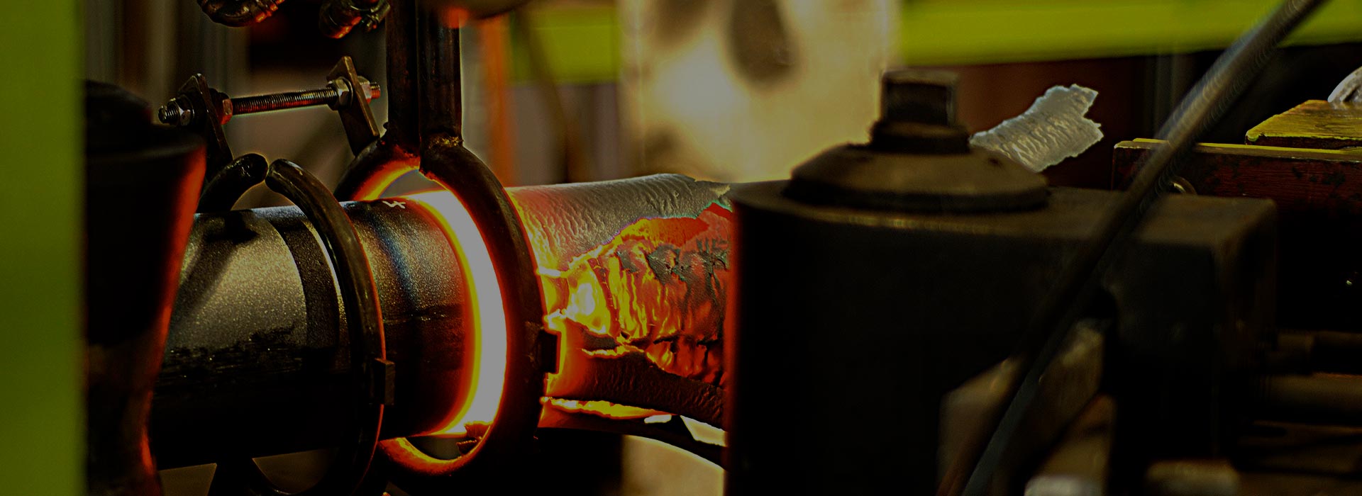
Induction Bending is a controlled means of bending pipes through the application of local heating using high frequency induced electrical power.
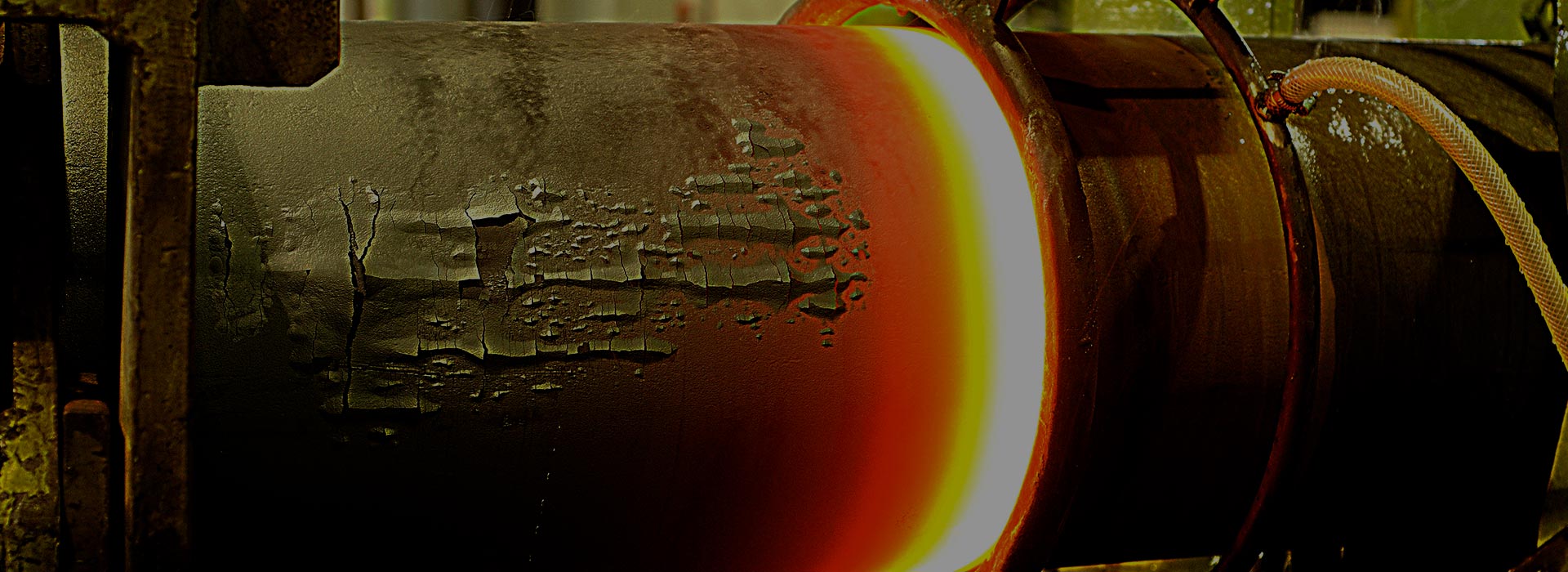
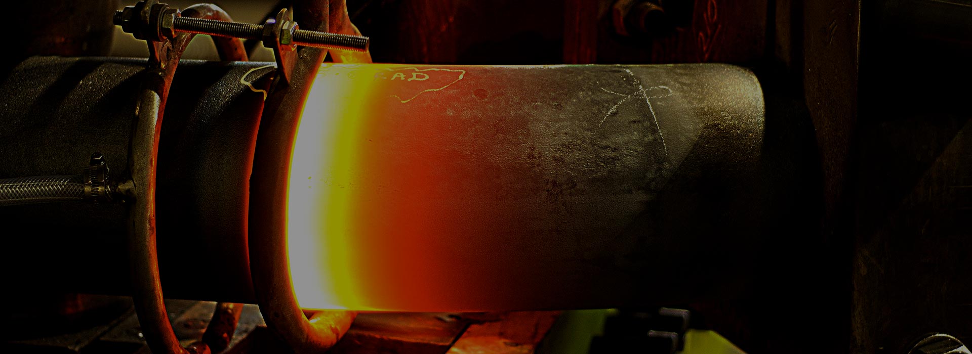
Originally used for the purpose of surface hardening steels, induction technology when used in pipe bending consists basically of an induction coil placed around the pipe to be bent. The induction coil heats a narrow, circumferential section of the pipe to a temperature of between 850 and 1100 degrees Celsius (dependant on the material to be formed). As the correct bending temperature range is reached, the pipe is moved slowly through the induction coil whilst the bending force is applied by a fixed radius arm arrangement.
As the bending occurs, the adjacent area forward of the heat band is water or air quenched (or may be allowed to cool naturally) thereby allowing the cool material to either side of the ‘heat band’ to retain the integrity of the original material as best as possible. This means of distortion control provides excellent dimensional accuracy and repeatability.
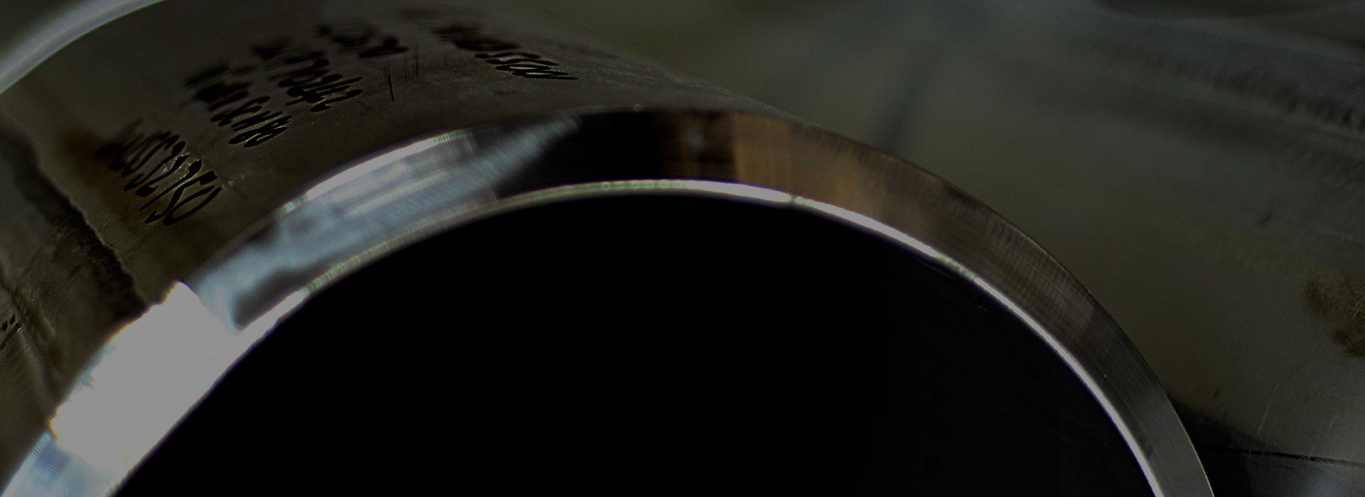
Achieved tolerances when forming induction bends are to some extent governed by the materials in hand and the required format of the finished product however the following are the minimum standards to which Induction Pipe Bending UK Ltd operate;
- Angle: + / – 0.5 degrees
- Radius: + / – 1.0% of nominal
- Linear distances: + / – 3.0mm up to & including 12” NB, + / – 5.0mm thereafter
- Linear plane: + / – 1.0% of centre line radius
Although induction bending produces excellent results as far as physical properties are concerned, it must be noted that there are two important considerations required – firstly the reduction in wall thickness at the outside (extrados) of the bend and secondly the degree of ovality which is present.
Neither of these factors can be guaranteed prior to bending however historical data allows anticipated values to be produced.
| Diameter to Radius Ratio | Anticipated reduction in wall thickness (from actual starting thickness) |
|
2.0 (Radius/OD) 2.0 (Radius/NB) |
18.0% 20.0% |
|
2.5 (Radius/OD) 2.5 (Radius/NB) |
16.0% 17.0% |
|
3.0 (Radius/OD) 3.0 (Radius/NB) |
15.0% 16.0% |
|
4.0 (Radius/OD) 4.0 (Radius/NV) |
9.0% 10.0% |
|
5.0 (Radius/OD) 5.0 (Radius/NB) |
8.0% 8.0% |
|
6.0 (Radius/OD) 6.0 (Radius/NB) |
6.0% 6.0% |
| Diameter to Radius Ratio | Anticipated Ovality Percentage ((max. OD – min. OD) /nominal OD * 100 | |||||||
|---|---|---|---|---|---|---|---|---|
| OD /WT =’10’ | OD /WT =’20’ | OD /WT =’30’ | OD /WT =’40’ | OD /WT =’50’ | OD /WT =’60’ | OD /WT =’70’ | OD /WT =’80’ | |
| 2.0 (Radius/OD) 2.0 (Radius/NB) | 3.7 4.0 | 4.7 5.1 | 5.7 6.2 | |||||
| 2.5 (Radius/OD) 2.5 (Radius/NB) | 3.2 3.5 | 3.8 4.1 | 4.7 5.1 | 5.5 6.0 | ||||
| 3.0 (Radius/OD) 3.0 (Radius/NB) | 2.8 3.0 | 3.4 3.7 | 4.2 4.6 | 4.8 5.2 | 5.5 6.0 | |||
| 4.0 (Radius/OD) 4.0 (Radius/NV) | 2.3 2.5 | 2.8 3.0 | 3.3 3.6 | 3.8 4.1 | 4.3 4.7 | 4.8 5.3 | ||
| 5.0 (Radius/OD) 5.0 (Radius/NB) | 2.1 2.3 | 2.5 2.7 | 2.8 3.0 | 3.3 3.6 | 3.7 3.6 | 4.1 4.6 | 4.5 4.9 | |
| 6.0 (Radius/OD) 6 .0 (Radius/NB) | 1.8 2.0 | 2.3 2.5 | 2.6 2.8 | 2.8 3.0 | 3.3 3.9 | 3.6 4.1 | 3.8 4.1 | 4.4 4.9 |